Guidelines for verifying Wheatstone bridge load cells, strain gage signal conditioning amplifiers, and diagnosing signal drift or offset faults.
The load cell and amplifier can easily be tested together by observing the voltage (amplifier output which should be fed into torque input terminals on the back of the controller) while changing the load on the load cell. Unloaded, the amplifier should have a small DC voltage (the zero voltage). As load is applied, this voltage should increase linearly proportional to the applied load.
If the voltage decreases when applying load in nominal loading direction, reverse the Sig+ and Sig- lines on the amplifier; this will cause the voltage to increase with applied load. When the load is removed, the voltage should decrease back to the initial "zero voltage". If the assembly does not behave as indicated, it is likely that there is a problem with the load cell wiring and you should proceed to the troubleshooting section below.
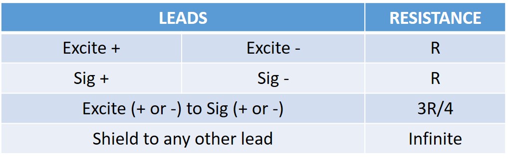
The amplifier in the unit is designed to work with standard Wheatstone bridge configuration 4-wire load cells with resistance between 100 to 450 ohms. The excitation voltage (Excite+ relative to Excite-) is either 5V or 10V depending on the voltage selector switch on the back of the amplifier. When functional, Sig+ and Sig- lines should both be at approximately 1/2 the excitation voltage.
Connecting a voltmeter (set to DC mV scale) between Sig+ and Sig-, you should see a very small voltage (a few mV) which changes linearly with load. If the excitation voltage is properly applied and you do not get a repeatable and linear change in the Sig+ and Sig- voltage, it is likely that your load cell is improperly hooked up, one of the leads is broken, or the load cell itself is damaged.
Any one of these faults may lead to signal drift, high noise levels, no signal output, or the signal pegging at max/min rail voltages.
Our engineering team can assist with dyno calibration, strain gage signal conditioning, and custom controller setups.
Contact Technical Support